


Releasing Panels
Releasing Control Module
The Gamewell-FCI Releasing Control Modules are specifically designed for fire suppression releasing applications in the E3 Series System.
Overview
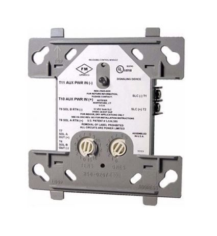
The Gamewell-FCI, Releasing Control Modules are specifically designed for fire suppression releasing applications in the E3 Series System. Power to the release agent solenoid(s) runs through this module to offer superior full-time monitoring and supervision. The Releasing Control Modules supervises the wiring to the connected load and reports the status to the panel as Normal, Open and Short Circuit. Releasing Control Modules Can power one 24V or two 12V solenoids and Mounts in a standard 4in (10.16 cm) junction box.
Features & Benefits:- Redundant protocol for added protection
- Configurable for Class A or Class B operation
- Supports external supply voltage monitoring
- Includes a panel controlled status LED
- Offers analog communications
- Uses rotary address switches
- Has a low standby current
- Provides the Velociti Series operation
- FM Approved
- ISO 9001 Certification
- UL Standard: UL 864 9th Edition
- UL: S1949
Specifications
Others
- External Supply Voltage
- 24 DC volt
- Maximum Activation Current
- 2 AMP
- Standby Current
- 6.4 4K
- Signaling Line Circuit Maximum Activation Current
- 9 4K
- Maximum Operating Humidity
- 95 Percentage
- Compatible Environments
- This system meets NFPA requirements for operation at 0 - 49°C/32 - 120°F and at a relative humidity 93% ± 2% (non-condensing) at 32°C ± 2°C (90°F ± 3°F). However, the useful life of the system's standby batteries and the electronic components may be adversely affected by extreme temperature ranges and humidity. Therefore, it is recommended that this system and its peripherals be installed in an environment with a normal room temperature of 15 - 27°C/60 - 80°F.
- Maximum Operating Voltage
- 32 V DC
- Wiring Configuration
- Class A
- Class B
- Minimum Operating Voltage
- 15 V DC
- Solenoid Supervisory Loop Current
- 30 4K
- Minimum Operating Humidity
- 10 Percentage
- Signaling Line Circuit Maximum Average Operating Current
- 700 µA
- Solenoid Supervisory Loop Voltage
- 3.3 VLT
- External Supply Voltage : 24 DC volt
- Maximum Activation Current : 2 AMP
- Standby Current : 6.4 4K
- Signaling Line Circuit Maximum Activation Current : 9 4K
- Maximum Operating Humidity : 95 Percentage
- Compatible Environments : This system meets NFPA requirements for operation at 0 - 49°C/32 - 120°F and at a relative humidity 93% ± 2% (non-condensing) at 32°C ± 2°C (90°F ± 3°F). However, the useful life of the system's standby batteries and the electronic components may be adversely affected by extreme temperature ranges and humidity. Therefore, it is recommended that this system and its peripherals be installed in an environment with a normal room temperature of 15 - 27°C/60 - 80°F.
- Maximum Operating Voltage : 32 V DC
- Wiring Configuration : Class A|Class B
- Minimum Operating Voltage : 15 V DC
- Solenoid Supervisory Loop Current : 30 4K
- Minimum Operating Humidity : 10 Percentage
- Signaling Line Circuit Maximum Average Operating Current : 700 µA
- Solenoid Supervisory Loop Voltage : 3.3 VLT
Sort
Others
Document Title
Document Type
Language
Brand
File Size
Data Sheet
Document Title
Document Type
Language
Brand
File Size
Catalog
Document Title
Document Type
Language
Brand
File Size
Document Title
Document Type
Language
Brand
File Size
Name
Description
File Size
Date
Size
